What's inside
As an Amazon Associate I earn from qualifying purchases. This post may contain affiliate links at no extra cost to you.
What we cover
MIG Welder Description: Features, Uses, and Buying Guide
A MIG welder is a wire-feed welding machine that continuously supplies a consumable metal wire while an electric arc melts the wire and the workpiece together, usually with shielding gas protecting the molten weld from air.
What the Main MIG Welder Components Do
Understanding the parts makes a specification sheet much easier to evaluate. A machine can have an impressive maximum amperage yet be unsuitable for your projects if its wire-feed system, duty cycle, or minimum output is poorly matched.
As an Amazon Associate we earn from qualifying purchases at no extra cost to you.

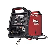

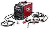
Power source and controls
The power source converts input electricity into controlled welding current. Entry-level machines commonly accept 120 volts, while larger shop welders may require 240 volts. Dual-voltage models can use either, which is useful when moving between a household outlet and a workshop circuit.
Voltage controls the arc length and strongly affects weld-bead shape and penetration. Higher voltage generally produces a longer, flatter arc; too much can cause excessive spatter, undercutting, or burn-through. Amperage is closely related to wire-feed speed and determines how much metal the arc can melt. Many modern machines coordinate these settings automatically, while manual machines require the operator to set both.
Wire spool, drive rolls, and liner
The spool holds the welding wire. Drive rolls grip and push it through the gun cable, and the liner guides it from the machine to the contact tip. A tension knob must be tight enough to feed wire consistently but not so tight that it deforms the wire.
Drive rolls are matched to the wire diameter and profile. Knurled rolls grip flux-cored wire, while smooth V-groove rolls are commonly used for solid wire. Using the wrong roll can cause slipping, bird-nesting, or inconsistent wire speed.
Welding gun, contact tip, and nozzle
The gun carries the welding current, wire, shielding gas, and trigger controls. The contact tip transfers electrical current to the wire and must match the wire diameter. It is a wear item: spatter, heat, and a loose fit can enlarge the tip opening and make the arc unstable.
The nozzle directs shielding gas around the arc. Keep it free of spatter and trim away buildup before it restricts gas flow. Anti-spatter spray can reduce maintenance, but excessive spray can contaminate the workpiece and weld.
Ground clamp and work lead
The ground clamp completes the electrical circuit through the workpiece. It needs clean, firm contact with bare metal. A weak clamp can produce an erratic arc that is easily mistaken for a machine fault.
Gas regulator and solenoid
Solid-wire MIG welding normally uses a shielding-gas cylinder, regulator, hose, and machine solenoid. A common gas for mild steel is a 75% argon/25% carbon dioxide blend; pure carbon dioxide is less expensive and can provide deeper penetration, but it usually creates more spatter. Aluminum commonly uses 100% argon.
Flux-cored wire can be used without external gas, depending on its type. Self-shielded flux-cored wire is practical outdoors because wind does not disperse a gas shield, but it generally produces more smoke, slag, and cleanup.
How MIG Welder Specifications Translate to Real Work
| Specification | Typical useful range | What it means in practice |
|---|---|---|
| Input power | 120 V, 240 V, or dual voltage | 120 V suits light fabrication; 240 V supports higher sustained output |
| Output current | 30–140 A on compact units; 40–250 A on shop machines | Higher amperage handles thicker steel, provided the duty cycle and circuit support it |
| Duty cycle | 20%–60% at a stated amperage | Determines how long the welder can run during a 10-minute period before cooling |
| Wire diameter | 0.023, 0.030, 0.035, and 0.045 inch | Smaller wire gives better control on thin material; larger wire deposits metal faster |
| Rated material capacity | About 1/8 inch to 1/2 inch steel per pass, depending on machine | Indicates realistic work range, not the maximum thickness that can be joined with multiple passes |
| Gas flow | 20–30 cubic feet per hour for many indoor jobs | Too little causes porosity; too much can create turbulence and draw air into the shield |
Voltage and amperage
For thin sheet metal, a welder needs a sufficiently low minimum output and fine control. A machine that starts at 50 or 60 amps may be difficult to use on automotive panels or 20-gauge steel without burn-through. Short tack welds, correct wire speed, and brief pauses also help manage heat.
For 1/8-inch mild steel, a compact 120-volt machine in the roughly 90–140 amp class is often adequate for short welds. A 1/4-inch plate may require around 180–220 amps, beveling, preheating in some situations, and more than one pass. Always follow the machine’s chart and the wire manufacturer’s settings rather than treating amperage estimates as universal rules.
Duty cycle
A 30% duty cycle at 90 amps means the welder can operate for three minutes out of a ten-minute period at that output, followed by seven minutes of cooling. Duty cycle is measured at a particular amperage, so a rating at 60% and 130 amps does not mean the machine can deliver 60% at its maximum setting.
For occasional brackets and repairs, a 20%–30% rating may be sufficient. Frequent frame fabrication, long seams, or production work justify a machine with at least a 40%–60% rating at the current you actually plan to use.
Wire size and type
- 0.023 inch solid wire: useful for thin sheet steel and low-heat work.
- 0.030 inch solid wire: a versatile choice for light and medium mild-steel fabrication.
- 0.035 inch solid wire: better for heavier steel and higher deposition rates.
- 0.030 or 0.035 inch self-shielded flux core: practical outdoors and for dirty steel, but it requires slag removal and correct polarity.
- 0.035 or 0.045 inch wire: suited to larger machines, thicker material, and longer welds.
Wire-feed speed affects amperage: increasing speed generally increases current and deposition, while reducing it lowers heat. Wire that stubs into the work indicates insufficient voltage, excessive wire speed, or an incorrect stick-out. A long, wandering arc can indicate too much voltage, too little wire speed, or excessive contact-tip distance.
Choosing a MIG Welder by Situation
| Your situation | Recommended configuration | Why |
|---|---|---|
| Beginner, occasional repairs, limited budget | 120 V, 130–160 A, 0.023–0.030 inch wire, gas or flux-core capability | Simple setup and enough capacity for brackets, carts, gates, and light steel |
| Automotive sheet metal | Low minimum output, 0.023 inch wire, accurate voltage adjustment, 75/25 gas | Fine control reduces burn-through and makes short tack welds easier |
| Small fabrication shop | Dual voltage, 180–220 A, 0.030–0.035 inch wire, at least 40% duty cycle | Handles varied material and permits longer welding sessions |
| Outdoor work | Self-shielded flux-core mode, robust leads, adjustable inductance if available | Eliminates dependence on shielding gas in breezy conditions |
| Frequent heavy fabrication | 240 V, 220–300 A, 0.035–0.045 inch wire, 50%–60% duty cycle | Supports thicker steel, higher deposition, and repeated long welds |
A Practical Setup Sequence
- Identify the material and thickness. Remove paint, rust, oil, and mill scale near the joint. Contamination causes porosity and weak fusion.
- Select wire and polarity. Solid wire with gas commonly uses electrode-positive polarity; self-shielded flux-core wire often uses electrode-negative polarity, but the wire label takes priority.
- Install the matching drive roll, liner, contact tip, and spool. Confirm that the wire diameter is printed on each component.
- Set gas flow and check for leaks. Indoors, start near 20–30 cubic feet per hour and adjust only when conditions require it. Keep the cylinder upright and secured.
- Set voltage and wire speed from the chart. Make a test bead on scrap of the same thickness. Listen for a steady crackling arc and inspect for even fusion.
- Weld with a short stick-out. Around 3/8 inch is a useful starting point for many solid-wire applications. Maintain a consistent travel angle and speed.
- Inspect and clean. Remove slag from flux-core welds, brush the bead, and check for pinholes, undercut, cold lap, and incomplete fusion.
Ownership Costs and Durability
The purchase price is only part of the cost. General market ranges in 2026 are roughly $200–$500 for basic 120-volt machines, $500–$1,200 for capable dual-voltage shop units, and $1,200 or more for higher-output professional equipment. Add wire, contact tips, nozzles, liners, gas refills or rental, gloves, and replacement regulators.
Contact tips and nozzles usually wear first because they face heat and spatter. Liners eventually collect debris, especially when dirty or rusty wire is used. Drive rolls can wear or become contaminated. Store solid wire in a dry place, cover the spool when not in use, clean the gun regularly, and do not drag the gun cable across sharp corners.
The most common buying mistake is choosing by maximum amperage alone. Confirm the machine’s minimum output, duty cycle at a useful current, included accessories, wire diameter range, input-circuit requirements, polarity options, and availability of replacement parts. For most home fabricators, a dual-voltage machine with stable low-current control and a 30%–40% duty cycle offers more practical value than a compact unit advertised with an unusually high peak amperage.