What's inside
As an Amazon Associate I earn from qualifying purchases. This post may contain affiliate links at no extra cost to you.
Most MIG welding wire feed problems are caused by the wire path rather than the welder itself, so diagnose the spool tension, liner, drive rolls, contact tip, torch bends, and motor pressure in that order.
As an Amazon Associate we earn from qualifying purchases at no extra cost to you.


What we cover
Start with the symptom
A wire-feed fault usually appears as one of four symptoms: the wire slips at the drive rolls, the feed motor surges or stalls, the wire bird-nests behind the rolls, or the wire burns back into the contact tip. Each points to a slightly different restriction, but changing parts at random can hide the real cause.
- Wire slips or feeds slowly: check spool drag, dirty or incorrect drive rolls, excessive liner friction, and insufficient motor pressure.
- Bird-nesting: look for a blocked liner, oversized liner, loose or misaligned rolls, or a contact tip that is too tight.
- Burnback: inspect contact-tip size, wire speed, stick-out, and whether the wire is intermittently stopping.
- Uneven, pulsing feed: suspect a rough liner, damaged wire, spool tangles, worn rolls, or a bent torch lead.
Before opening the machine, switch off power, close the shielding-gas cylinder, and release drive-roll pressure. Never pull a tangled wire through the torch while the rolls are turning.
Diagnostic order for MIG wire feed problems
1. Check spool tension and the wire path
The spool should rotate smoothly with only enough brake tension to stop it from coasting when feeding stops. Too much tension makes the motor work against the spool; too little allows the spool to overrun and form loose loops. Both conditions can look like a weak feed motor.
With the wire disconnected from the liner, rotate the spool by hand. It should not bind, scrape, or wobble. Check that the spool adapter matches the spool bore and that the wire has not crossed underneath itself. A crossed loop can suddenly tighten and stop the feed.
For a typical 15 kg steel spool, begin with light brake tension and increase it only until the spool stops promptly when the feed trigger is released. Do not use spool tension to compensate for a dirty liner or excessively tight drive rolls.
2. Match the liner to the wire
The liner guides the wire from the inlet guide to the contact tip. If it is too small, the wire drags; if it is too large, the wire can wobble, snag, and feed inconsistently. The liner must also be fully seated, cut squarely, and free from crushed sections.
| Wire type | Common wire diameters | Typical liner material | Practical liner guidance |
|---|---|---|---|
| Solid steel | 0.023, 0.030, 0.035, 0.045 in | Steel or polymer | Use a liner rated for the wire range; avoid excessive clearance |
| Stainless steel | 0.030, 0.035, 0.045 in | Polymer or dedicated stainless liner | Keep the path clean; stainless wire is less tolerant of drag |
| Aluminum | 0.030, 0.035, 0.047 in | Low-friction polymer | Use a short, smooth torch path and a liner designed for aluminum |
| Flux-cored wire | 0.030, 0.035, 0.045 in | Steel or polymer, depending on wire | Remove accumulated dust; abrasive flux can wear the path |
As a rough sizing rule, a liner intended for 0.030–0.035-inch wire should not be used as a universal solution for every diameter. Follow the liner manufacturer’s stated range. When replacing one, compare its overall length with the original and make sure the liner does not protrude into the contact-tip seating area.
3. Set the drive rolls correctly
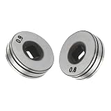
Drive rolls must match both the wire diameter and the wire type. V-groove rolls are normally used for solid steel and stainless wire. U-groove rolls are preferred for soft aluminum. Knurled V-groove rolls are commonly used for flux-cored wire because they grip without requiring extreme pressure, although they can mark solid wire and create debris.
Misaligned rolls are a frequent cause of feed faults. The wire should enter the inlet guide, pass through the center of the groove, and leave toward the outlet guide in a straight line. If the wire climbs out of the groove or rubs one side of a guide, correct the alignment before tightening anything.
Drive-roll pressure should be high enough to feed the wire without slipping, but not so high that it flattens the wire. A useful check is to straighten the torch and hold the wire against a clean wooden surface while feeding at a moderate speed. Increase pressure gradually until the wire stops slipping. If the roll leaves a deep groove, creates metal dust, or deforms the wire, back the pressure off.
4. Inspect the contact tip
The contact tip transfers welding current to the wire, so it must be the correct size and in good condition. A tip marked 0.030 inch is intended for approximately 0.030-inch wire, not for a visibly worn 0.035-inch wire. A tip that is too tight causes drag and burnback; a worn or oversized tip allows the arc to wander and can produce erratic starts.
Replace the tip if the bore is oval, chipped, discolored from overheating, or obstructed by spatter. Contact tips are inexpensive consumables, but using the wrong size repeatedly can make a healthy wire-feed welding machine appear defective. Keep spare tips matched to each wire diameter you use.
5. Test the torch with gentle bends
A MIG torch that feeds correctly when straight but stalls when bent has excessive friction somewhere in the torch lead. Inspect the liner for a kink, a sharp bend near the machine connection, or a worn section near the neck. Long, tightly coiled torch leads create more resistance than a relaxed, gradual curve.
During diagnosis, lay the torch as straight as practical and feed several feet of wire. Then introduce one gentle bend at a time. If feed quality changes at a particular point, inspect that section rather than immediately replacing the motor. The same test is useful for aluminum, which is especially sensitive to liner friction and torch geometry.
6. Adjust motor pressure only after the path is right
The drive motor should not be asked to overcome faults elsewhere. If the spool, liner, rolls, and tip are correct, adjust motor pressure in small increments. Excessive pressure can crush soft wire, pack debris into the liner, and make later feeding worse. Insufficient pressure causes slipping, especially at higher wire-feed speeds.
When the wire jams, release the roll tension before pulling the wire backward. Cut away the damaged section and inspect the wire for a flattened spot. Re-thread from a clean section, because a flattened wire can continue to bind even after the original obstruction is removed.
Setup choices that prevent repeat failures
Use the smallest practical wire diameter for the job, but do not exceed the machine’s rated output. For example, 0.030-inch solid steel wire is a versatile choice for lighter fabrication, while 0.035-inch wire offers more deposition capacity for thicker material. Match the contact tip, liner, drive roll, and welding settings as a complete system.
Keep the wire covered when it is not in use. Rust, dust, and moisture increase liner contamination and can contribute to unstable arcs. Before each spool, blow dry compressed air through the accessible wire path if the manufacturer permits it. Do not oil a liner: lubricant can collect dust and contaminate the weld.
| Situation | Recommended starting approach | What to prioritize |
|---|---|---|
| Occasional home fabrication | 0.030-inch solid steel wire with matched V-groove rolls | Correct tip size, clean liner, simple adjustment |
| Frequent mild-steel work | 0.035-inch solid wire where machine output supports it | Spool braking, roll alignment, replacement consumables |
| Flux-cored outdoor work | Knurled rolls and a liner rated for flux-cored wire | Debris removal and moderate roll pressure |
| Aluminum fabrication | Low-friction liner and U-groove rolls | Short torch path, gentle bends, low drag |
When the problem may be electrical
If the wire path feeds smoothly with the contact tip removed but the motor still stops, surges, or changes speed without mechanical resistance, inspect the trigger circuit, motor connections, control board, and feed-motor brushes where applicable. Also check the machine’s input power and extension-cord arrangement. A long, undersized extension cord can cause voltage drop, although it is more commonly noticed as poor arc performance than as a purely mechanical feed fault.
At this stage, consult the machine’s service information or a qualified repair technician. Replacing a motor or control board before confirming the mechanical path is usually an expensive guess.
Ownership costs and parts that wear first
The contact tip is normally the fastest-wearing part, followed by the liner and drive-roll groove. Their service life depends on wire cleanliness, welding current, spatter, and how often the torch is bent. A practical maintenance kit includes several correctly sized contact tips, a spare liner, matching drive rolls, a tip-cleaning tool, and a brush for removing wire dust.
The cheapest long-term fix is often better setup rather than a larger motor. Correct spool tension, a clean liner, aligned rolls, and moderate pressure prevent most recurring MIG wire feed problems and protect the torch from damage. If all six checks pass and the fault remains, the machine may have an electrical control or motor issue rather than a normal consumable problem.
Frequently asked questions
Why does my MIG wire bird-nest at the rollers?
The wire is usually meeting resistance after the drive rolls. Check for a blocked or incorrectly sized liner, a tight contact tip, a kinked torch, or excessive roll pressure. Remove the damaged wire and re-thread from a clean section.
Can too much drive-roll tension cause feed problems?
Yes. Excessive pressure can flatten the wire, damage soft aluminum, wear the rolls, and push debris into the liner. Set only enough pressure to prevent slipping.
Why does wire feed correctly with the torch straight?
A straight torch reduces liner friction. If bending the torch causes stalling, inspect for a kink, crushed liner, sharp bend, or worn section near the torch neck or machine connection.