What's inside
- Quick welder electrical plug guide
- Start with the nameplate, not the welding-output number
- Choosing between common plug types
- Decision matrix: which setup fits your workshop?
- Extension cords: the limit is length, current, and voltage drop
- Worked power check: why 240 V can help
- Safe installation checklist
- Ownership realities: what wears out first
- Bottom line
- Related Guides
- Quick welder electrical plug guide
- Start with the nameplate, not the welding-output number
- Choosing between common plug types
- Decision matrix: which setup fits your workshop?
- Extension cords: the limit is length, current, and voltage drop
- Worked power check: why 240 V can help
- Safe installation checklist
- Ownership realities: what wears out first
- Bottom line
- Related Guides
As an Amazon Associate I earn from qualifying purchases. This post may contain affiliate links at no extra cost to you.
The right welder electrical plug is determined by the welder’s input voltage, maximum or rated input current, duty cycle, and the circuit already installed—not by the machine’s advertised welding amperage alone.
A compact 120-volt inverter may use a standard 5-15 plug, while a 240-volt machine commonly needs a 6-30, 6-50, or hardwired connection. Before buying a plug or cord, read the welder’s nameplate and installation manual, then match the plug, receptacle, breaker, wire size, and extension cord as one complete system.
As an Amazon Associate we earn from qualifying purchases at no extra cost to you.


What we cover
- Quick welder electrical plug guide
- Start with the nameplate, not the welding-output number
- Choosing between common plug types
- Decision matrix: which setup fits your workshop?
- Extension cords: the limit is length, current, and voltage drop
- Worked power check: why 240 V can help
- Safe installation checklist
- Ownership realities: what wears out first
- Bottom line
- Related Guides
Quick welder electrical plug guide
| Welder input | Typical nameplate input | Common plug or connection | Typical circuit | Best use |
|---|---|---|---|---|
| 120 V | 15–20 A | NEMA 5-15 or 5-20 | 20 A branch circuit, where required | Light fabrication, repairs, occasional use |
| 120 V | 25–30 A | Usually a dedicated twist-lock or hardwired connection specified by the manufacturer | Dedicated circuit sized to the manual | Higher-output operation where 120 V is supported |
| 240 V | 20–30 A | NEMA 6-30 or another specified 30 A plug | 30 A, two-pole breaker | Medium-duty MIG, TIG, or stick welding |
| 240 V | 40–50 A | NEMA 6-50 is common; confirm the manual | 50 A, two-pole breaker | Frequent workshop welding and higher output |
| 240 V | Over 50 A or three-phase | Manufacturer-specified industrial plug or hardwire | Dedicated circuit calculated by a qualified electrician | Production and heavy fabrication |
These are common arrangements, not universal substitutions. A NEMA 6-50 receptacle is not automatically suitable for every welder that operates at 240 volts. The plug’s current rating must agree with the equipment instructions and the branch circuit.
Start with the nameplate, not the welding-output number
A welder described as “200 amps” refers to maximum welding output. Its electrical demand can be substantially different. Find these specifications:
- Rated input voltage: commonly 120 V, 208 V, 230 V, or 240 V.
- Rated input current: the current associated with a stated output and duty cycle.
- Maximum input current: useful for circuit and overcurrent-protection planning.
- Duty cycle: the percentage of a 10-minute period the machine can weld at its rated output.
- Recommended breaker, receptacle, and conductor size: follow the manufacturer’s published requirements.
Voltage is not interchangeable. Connecting a 240-volt-only welder to a 120-volt receptacle can damage it or prevent operation, while a dual-voltage model must have its selector, plug adapter, and supply voltage configured correctly. Never rely on the receptacle shape alone; verify the voltage with an appropriate meter or have an electrician verify it.
Choosing between common plug types
NEMA 5-15 and 5-20: ordinary 120-volt connections
A NEMA 5-15 plug has two flat blades and a grounding pin and is normally associated with a 15-amp, 120-volt receptacle. A NEMA 5-20 plug has one blade turned sideways and requires a compatible 20-amp receptacle. A 5-20 plug should not be forced into a 5-15 outlet or replaced with a smaller plug.
Some small inverter welders can operate from a 15-amp circuit at reduced output, but a dedicated 20-amp circuit may be required for full performance. Shared circuits are a poor choice because grinders, lights, compressors, or heaters can cause nuisance trips and voltage drop.
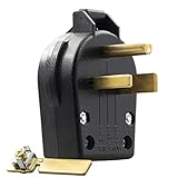
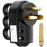
NEMA 6-30: a 30-amp, 240-volt option
The NEMA 6-30 is a two-pole, 250-volt-rated configuration commonly used for equipment requiring a 30-amp circuit. It has two hot conductors and a grounding connection; it does not use a neutral for a typical 240-volt welder. Install it only when the welder’s manual calls for this arrangement.
NEMA 6-50: common for 240-volt welders
The NEMA 6-50 is widely seen on 240-volt welding equipment and plasma cutters. It is a 50-amp-rated configuration with two hot conductors and grounding. Its familiarity does not make it a universal replacement. A machine designed for a 30-amp supply must not be protected by simply installing a 50-amp receptacle and breaker.
Twist-lock and hardwired connections
Twist-lock plugs can resist accidental separation in mobile setups, while larger equipment may be supplied without a plug for direct connection. Both require careful attention to conductor identification, grounding, enclosure strength, strain relief, and local electrical rules. Hardwiring is best left to a qualified electrician unless you are licensed and permitted to perform the work in your location.
Decision matrix: which setup fits your workshop?
| Situation | Practical choice | Why | Watch out for |
|---|---|---|---|
| Beginner, occasional repairs, no 240 V circuit | 120 V inverter with manufacturer-supplied 5-15 or 5-20 plug | Lowest installation cost and adequate portability | Reduced output, nuisance trips, and limited thick-material capacity |
| Regular garage welding and a suitable 240 V supply | 240 V welder with the specified 6-30 or 6-50 connection | Lower current at the same power and generally better high-output performance | Existing outlet may have the wrong voltage, breaker, or conductor size |
| One welder used at several locations | Dual-voltage machine with approved input adapters | Flexible transport between 120 V and 240 V supplies | Adapters do not increase circuit capacity or eliminate voltage drop |
| Long production sessions or multiple machines | Dedicated 240 V circuit, short cord, and electrician-designed installation | Better stability and less interruption from overloaded circuits | Shared receptacles, undersized feeders, and poor ventilation |
Extension cords: the limit is length, current, and voltage drop
An extension cord can turn a correct plug into an unsafe setup if its conductors are too small or the run is too long. Welding equipment has demanding starting and load currents, and a voltage drop may cause poor arc performance, overheating, or repeated breaker trips.
As a general workshop reference, a 12 AWG cord is often used for moderate 120-volt loads, while a 10 AWG cord is more appropriate for higher current or longer runs. A 240-volt welder may still require 10 AWG, 8 AWG, or a different cable entirely. The correct size depends on the welder’s input current, cord length, duty cycle, ambient temperature, and applicable electrical rules.
For example, suppose a machine draws 20 amps at 120 volts and the manufacturer permits an extension cord. A 25-foot, 12 AWG cord may be reasonable for an intermittent load, but a 100-foot cord of the same size creates substantially more resistance and heat. Moving to a shorter or heavier-gauge cord is safer than installing a larger plug. Never use a lightweight household “indoor” cord, coiled cord, damaged jacket, or cord with a hot plug.
- Use the shortest approved cord that reaches the work.
- Choose a cord rated for the full current and environment.
- Uncoil the cord completely during welding.
- Keep connectors dry, elevated from puddles, and protected from sparks.
- Do not connect multiple extension cords end to end.
- Inspect the plug, strain relief, blades, and insulation before each session.
Worked power check: why 240 V can help
For the same approximate power, current falls as voltage rises. Using the simple relationship current = watts ÷ volts, a 4,800-watt load would draw about 40 amps at 120 volts but about 20 amps at 240 volts. Real welders are not simple resistive heaters—their efficiency, power factor, and duty cycle matter—but the example explains why higher-voltage operation can reduce conductor current and voltage drop.
That does not mean a 240-volt outlet automatically makes a welder more powerful. Output is limited by the machine’s design, and the circuit still must be installed to the nameplate and local code.
Safe installation checklist
- Read the manual and nameplate. Record input voltage, maximum input current, breaker recommendation, and plug type.
- Identify the existing circuit. Confirm voltage, breaker rating, conductor size, grounding, and whether other loads share the circuit.
- Match every component. The breaker, receptacle, plug, cord, and machine must be compatible; upgrading only the receptacle is not an upgrade to the circuit.
- Use proper protection. Follow local requirements for grounding, GFCI protection, disconnects, and receptacle placement. A qualified electrician can assess older or improvised wiring.
- Provide clearance and ventilation. Keep the receptacle and cord away from hot metal, grinding sparks, shielding-gas cylinders, and standing water.
- Test before welding. Check for secure connections, correct voltage, abnormal heat, buzzing, discoloration, or a burning odor during a short initial run.
Do not defeat the grounding pin, use a two-prong adapter, replace a fuse with a larger one, or install a breaker that exceeds the circuit’s conductor rating. If the outlet is ungrounded, damaged, loose, warm, or of uncertain voltage, stop and have it inspected.
Ownership realities: what wears out first
Plugs and receptacles commonly deteriorate from loose contacts, repeated insertion, welding spatter, crushed cables, and heat. A loose receptacle can produce resistance at the connection, which creates more heat and further damages the contact. Replace discolored, pitted, cracked, or heat-softened components rather than cleaning around the damage.
Keep the welder’s input cable loosely coiled, never sharply kinked near the plug, and store it away from ultraviolet light and oils. Check strain reliefs periodically. If the plug becomes hot while the machine is operating within its specified load, disconnect it and investigate the receptacle, termination torque, cord gauge, and circuit capacity.
Bottom line
Choose the welder electrical plug only after confirming the machine’s input requirements and the workshop circuit behind it. A 120-volt 5-15 or 5-20 setup suits light, portable work; a properly installed 240-volt 6-30 or 6-50 circuit suits many higher-output machines; and heavy or unusual equipment may need a manufacturer-specified industrial connection or hardwiring. When voltage, current, breaker, conductor, receptacle, and extension cord all match, the welder is safer, more reliable, and less likely to suffer from nuisance trips or unstable arc performance.